BIG F'N 3D PRINTER BUILD
The Reprap's, Prusa's, and other 3D printers are great. I've printed many things with them that have allowed other projects of mine to progress much faster then making by hand or buying them online and modifying them. But... there comes a point where you need a part that is just too big for the print volume or you're just too lazy to print a bunch of small pieces and glue and fit them together. Specifically I would like to start helping the local shelters with custom prosthetic's for dogs or animals in general. Typical print volumes don't accommodate 1 piece designs.
That's when I said to myself, "Hmmm I'll just buy a bigger 3D Printer and save myself some time." :) Well, I looked on the internet for printers that have about a 8 cubic foot print volume and found that my budget can't compete with some of these offerings online. Having built a few DLP Resin 3D printers and filament based ones in the past, I had some aluminum extrusions, stepper motors, RAMPS controllers and what not sitting around.
I set out and built a 3D printer with at least a 8 cubic foot volume. It also turns out after having done that, it is too big to get out of my basement without disassembling it... :(
Note: I had fudged the print volume at 2 cubic feet. It's actually 8 cubic feet. 2' x 2' x 2'

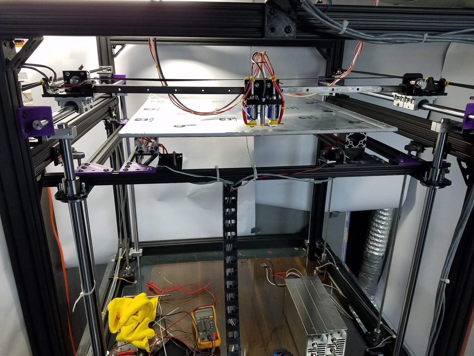
Nearly Complete Build. Two 60 Amp 12 Volt supplies and RAMPS 1.4 + Arduino Mega Control

If you look closely you can see a Reprap placed inside the Big F'er
Summary of Features:
- 8 Cubic foot print volume (capable of larger with minor changes - i.e bigger cast aluminum plate) - The reason I chose 1/4" Cast Aluminum plate was to make sure it was dimensionally stable when heated. Anything else will most likely warp over that big of an area.
- X, Y, Z end stops
- Filament runout sensors to pause BIG jobs
- Auto leveling bed (4 steppers to support heavy weight, but also allow auto leveling in addition to Z-probe) - used CNC shield board with 4 stepper drivers tied to the Z lines on the RAMPS 1.4 board.
- Smoke sensor (separate from main control system - tied to power supply inhibit lines) - no one wants to burn their house down.
- FLIR Lepton module to monitor and provide feedback on heat distribution for design improvements.
- Dual Bowden extruders (allow fast transits by minimizing weight of extruder sled)
- Heated bed (cast aluminum plate and four 280 watt silicone heating pads)
- Had been named "Big F'er" because I managed to hit my head many times working on it and assembling it. I apologize to anyone offended by this totally appropriate name.
- Inductive Z probe
Customized Marlin firmware: HERE
- RAMPS 1.4
- Dual Extruder
- Heated bed protection off (have fire/smoke sensor) - Plate warms slowly.
- 100k thermister for heated bed
- Calibrated for specific leadscrews and GT2 timing belt
- Intend to modify in future for 4 stepper based auto leveling.
FRAME
The first step is to build a rigid frame 3 feet square approximately. I used 3 foot long sections of 8020 2" x 2" 10 series extruded aluminum. With the 8 hole gussets this works very well and provides a rigid and stable frame.

Y-AXIS


Here's the base assembled with the Y-axis rods and X-axis mounted. Turns out the X-axis design got trashed because there was a little bit of sag over the long distance. You can see the working design below.
The STL for end mounts that were used for the 5/8" Y-axis rods are here. You may need to scale the print a little to get a tight fit on the rod.

The bearings used on the Y-axis sleds are SWD10 NB Systems Ball Bushing 5/8" inch Open Block Linear Motion.


They were redesigned to use a linear rail and matching bearing. I got these off ebay. Brand new, they are fairly expensive. The sleds have holes to screw in the standard endstop switches for the X and Y axis.


The idler portion is simply an 8mm bolt with nuts on either end sandwiching some skate bearings.


One issue encountered with the Y-axis was some sag (the whole reason I redesigned the X-axis... oh well) The 5/8" rods are great, but over 3 feet there is just enough sag to make me question the quality of prints. So not wanting to start over I designed a SAG fixer :) All it really is, is a mount below each Y-axis rod with an 8mm threaded shaft that allows me to push ever so slightly on the center of each Y-axis rod to make it straight. The STL is HERE.


Z-AXIS AND BED


The brass nuts are attached to the plate bed with these mounts. The STL is HERE.


Each NEMA 17 stepper is screwed into a mounting plate (STL HERE) that is then screwed onto the 8020 extrusions.


Here are the Z axis drives mounted. Notice the 80/20 cross bars that the pillow blocks attach to. You may need to play with the height etc to make sure everything is square.


The linear screws aren't enough to keep the Z bed stable and rigid. I also installed 4 - 20mm linear rods.


The rods are attached with Milling Machine SK20 20mm Bore Linear Rail Shaft Support Rod Bracket . LMF20UU Linear bearings are then slid on and attached to the Z bed via mounts (STL HERE)


Here is a picture of the Z bed with the plate upside down. The 12" square silicone heating pads are attached to the back of the cast aluminum plate with 3M 468MP Adhesive Transfer Tape.

The silicone heating pads are driven by TWO RepRap Champion 3D Printer Heated Bed Power Module Upgrade. I also used a standoff to mount a small 40mm fan to each. Ideally I would like to have one driving each pad, this will allow you to heat things up faster with a properly specced power supply. I put two pads in series for each power module and it's a little slow.


Due to the length of my 20mm shaft and Z axis leadscrews I had to put 2" sections of 80/20 extrusions on the Z bed to offset the cast plate up. This worked perfectly. I also used Ruland MSP-20-F 20mm split ring clamps to set the limit for range on the Z axis. Currently my homing operations simply stall out the Z motors if things aren't level.
The Z end stop mount (STL HERE). Is placed on the cross beams above each Z axis linear screw (or approximately around). The theory is each end stop will prevent it's stepper from stalling at the split ring clamp and the bed will level based on that. However I have only wired one of the Z end stops to Z min on the RAMPS 1.4 board.

X CARRIAGE
The X carriage was fairly easy to assemble. There are three STL files. The main carriage (STL HERE). The clamp mounts for the E3D nozzles (STL HERE); and the belt connector and end stop unit (STL HERE).


The bowden extruders and filament out sensor were mounted to the top cross beam.


The runout sensor mount STL is HERE. It uses the same endstop switch as all the others. You may need to fiddle with the metal spring clip on the switch to get it to work without snagging. Designed for 1.75mm filament.

Have a beer and relax...


Video of the very first test case (40mm cube)
Kept the protective plastic on the build plate until I knew the heads wouldn't crash into it.
Don't even bother printing PLA onto a bare aluminum build plate unless you can crank up the temp.
Gluestick works very well as a surface treatment. PLA stuck very well on a build plate at 40 deg C

Electrical


Most wiring is fairly standard for a RAMPS 1.4 configuration. Exceptions are noted below. The actual cabling is 4 conductor shielded wire:

Heated Bed:
The heated bed utilizes the High Power heated bed module. Two silicone heating pads are tied in series then wired to the heated bed output of the module. Same with the other two silicone mats. 12 Volts is wired into both modules. The control inputs are placed in parallel and wired to the heated bed output of the RAMPS 1.4.

Z-AXIS Steppers:

Currently... To drive the 4 Z-axis steppers I used a CNC Shield I had. I bridged the X,Y,Z, and A step lines and connected them to the RAMPS 1.4 Z stepper STEP line. I did the same with the DIR lines. I took 5 volts and ground from the RAMPS 1.4 board and connected it to the CNC Shield too. The Z enable line was then bridged and 12 volt power applied. Works great :)
LED Lighting
Got a roll of 12 volt LED lighting i'm going to tie into the power.

NOTES:
The electronics enclosure is based on this thingiverse posting: https://www.thingiverse.com/thing:1029926
The bowden extruder stepper motors should be atleast 2 amp 84 oz-in. I was having some lost steps given the resistance through the length of teflon tubing to the extruder end.
The thermistor attached to the center of the heated plate should have some thermal grease added. I secured mine down with kapton tape.
The 10 series aluminum extrusions are great, however if you don't get the order of assembling things right these drop-in nuts can be a timesaver :)
UPDATES:
Thermal images are taken with FLIR Lepton module at 80x60 resolution. Wish it were a higher resolution. Oh well..
Thermals Image of left nozzle at 220 deg C and right nozzle off:
Thermal Image of underside of build plate while warming up:

Test Print:
40mm Cube - No skirt or brim. Turns out it needs it with a bed temp of only 40 deg C. Notice the peeling on the right side.

Parts List Summary (Total Cost Approx. $2000):
BuddhaFett Test Print: 0.2 layer height. Need to up the retract amount, getting a little oozing from transitions. :)

Much more to come. I plan on detailing more of the wiring and posting the smoke/fire cutoff system.
Any questions please don't hesitate to ask in the comments.
Any Bitcoin donations would be greatly appreciated, and help fund any current & future projects.